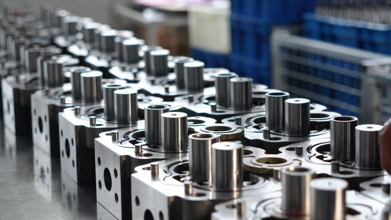
The gear pump category is aluminum gear pump, lightweight weight is an advantage of aluminum alloy, so that it is more convenient in the movement and installation process. Save the customer's cost on transportation.
Gear pump made of cast iron material has high mechanical strength and toughness, but also has heat resistance, corrosion resistance, wear resistance and other special properties
The internal gear pump can be reversed, as long as the motor steering can be replaced; The pump body can be turned, and the import and export positions are at right angles, which is convenient to select the import and export positions;
Single gear pump is a mechanical pump whose basic structure is composed of two gears, one of which drives the other gear. The two gears are usually concentrically mounted, and the meshing space between them forms a closed chamber.
Double gear pump is a liquid conveying device that consists of the meshing of two gears. The two gears are usually concentrically mounted, forming an enclosed space by meshing gears with each other.
Triple gear pump has triple displacement, which is good in the performance of transferring hydraulic oil, and is suitable for mechanical equipment manufacturers with high transmission requirements.
Multiple Gear Pump is generally customized, customers can customize their own gear pump according to their own equipment needs
Supplying a variety of hydraulic gear pumps for construction machinery. Our hydraulic gear pumps deliver superior power and control to excavators, maximizing digging performance and increasing productivity during the machinery working time. Experience seamless operations and improved excavation efficiency.
How important is it to provide dimensions when manufacturing hydraulic gear pumps: Hydraulic gear pump is the power element in the hydraulic transmission system, which is driven by the prime mover, takes the mechanical energy from the output power of the prime mover and converts it into the pressure energy of the fluid to provide the system with pressurized fluid. Then, at the place where work needs to be done, the actuating element converts the fluid pressure energy into mechanical energy and outputs it to the gear pump. Therefore, reasonable hydraulic gear pump size design and selection for the performance of the hydraulic system and the use of the effect is very important. Hydraulic gear pump size development: Hydraulic gear pump size refers to the design, manufacture and use of hydraulic gear pumps in the process, the provisions of its size range, tolerances, inspection methods and technical requirements and other aspects of the national standard. The development of hydraulic gear pump size is to ensure the quality and performance of hydraulic gear pumps, while making different manufacturers of hydraulic gear pumps have interchangeability. Then we need to confirm what size parameters before manufacturing hydraulic gear pumps? 1. Gear diameter Gear diameter is one of the important parameters of the internal gear pump, which determines the pump flow and pressure. Usually, the larger the gear diameter, the higher the flow rate, but the lower the pressure. Conversely, the smaller the gear diameter, the smaller the flow rate, but the higher the pressure. Therefore, in the design of gear pumps, according to the specific requirements to determine the gear diameter. 2. gear teeth Gear teeth is another important parameter of the gear pump, which determines the size of the gear and the number of teeth. Usually, the larger the gear module, the smaller the number of teeth, the larger the gear. Conversely, the smaller the gear module, the more teeth, the smaller the gear. In the design of internal gear pumps, according to the specific requirements to determine the gear module. 3. Pump body length Pump body length is another important parameter of the internal gear pump, which determines the pump flow and pressure. Usually, the longer the length of the pump body, the greater the flow, but the lower the pressure. Conversely, the shorter the length of the pump body, the smaller the flow rate, but the higher the pressure. In the design of internal gear pumps, need to determine the length of the pump body, according to the specific requirements of use. 4. Shaft diameter Shaft diameter is another important parameter of the internal gear pump, which determines the pump's load-bearing capacity and stability. Usually, the larger the shaft diameter, the stronger the carrying capacity of the pump, the better the stability. Conversely, the smaller the shaft diameter, the weaker the carrying capacity of the pump, the worse the stability. In the design of internal gear pumps, you need to determine the shaft diameter according to the specific requirements of use. Sample graph: The application of hydraulic gear pump size can be from the following aspects 1. Hydraulic gear pump design and manufacturing: hydraulic gear pump size can be used as a basis for hydraulic gear pump design and manufacturing, to ensure that the hydraulic gear pump dimensions and tolerances in line with the requirements, so as to ensure that the performance and quality of hydraulic gear pumps. 2. Hydraulic gear pump selection: hydraulic gear pump size can be used as a basis for the selection of hydraulic gear pumps, to help users choose the appropriate hydraulic gear pumps, so as to ensure that the performance of the hydraulic system and the use of the effect. 3. Hydraulic gear pump maintenance and overhaul: hydraulic gear pump size can be used as a hydraulic gear pump maintenance and overhaul basis to help users carry out maintenance and overhaul of hydraulic gear pumps, thereby extending the service life of hydraulic gear pumps. Note:This article was inspired by the internet. If you have more unanswered questions you can contact us.
Read MoreHydraulic gear pump is an energy conversion device, its role is to make the flow movement, the mechanical energy into fluid energy. The pump is a power component in the hydraulic transmission system, driven by the prime mover, and takes out the mechanical energy from the output power of the prime mover, and converts it into the pressure energy of the fluid to provide the pressure oil for the system Hydraulic gear pump has the following advantages: 1. High efficiency: hydraulic gear pump usually has a high mechanical efficiency, can effectively convert the input mechanical energy into hydraulic energy, improve the overall efficiency of the system. 2. Compact design: Hydraulic gear pumps usually have a compact design that allows them to be easily installed and arranged when space is limited. 3. Simple structure and cheap price: hydraulic gear pump is composed of fewer parts and relatively simple structure, so it has high reliability and easy maintenance. 4. Low working requirements and wide application: hydraulic gear pump can be used in a variety of hydraulic systems, including construction machinery, industrial machinery, automotive, aerospace and other fields, with a wide range of applications. 5. Good self-priming performance: hydraulic gear pumps usually have good self-priming performance and can start and run quickly under low pressure conditions. 6. Low noise and vibration: Due to its simple structure and smooth operation, hydraulic gear pumps usually have low noise and vibration levels, which helps to improve the comfort and stability of the system. In general, the hydraulic gear pump has many advantages in the hydraulic transmission system, making it one of the widely used hydraulic components.
Read MoreI believe that all engineers have encountered various malfunctions of hydraulic gear pumps in your work. So how should we troubleshoot when hydraulic gear pumps malfunction? Here are some common troubleshooting tips: Fault phenomenon Cause Analysis Troubleshooting Oil pump does not discharge oil 1. The oil pump does not rotate, the rotation speed is low, and the rotation direction is wrong. 2. The oil pump sucks air, there is insufficient oil in the oil tank, and the oil filter is clogged. 1. Check whether the key has fallen off, adjust the speed, and correct the direction of rotation. 2. Fill the fuel tank, clean the filter, and exhaust. The pressure cannot be reached 1. The system relief valve is out of adjustment and the pressure gauge display is inaccurate. 2. The internal leakage of the oil pump is too large. 1. Repair the relief valve or pressure gauge. 2. Inspect the oil pump. leakage 1. The oil pump shaft oil seal or sealing ring is damaged. 2. The fastening bolts are loose. 1. Replace the oil seal or sealing ring. 2. Tighten the bolts. Abnormal fever 1. The oil pump is running at overspeed. 2. The load pump is not unloaded. 3. The fuel tank has insufficient oil, the capacity is too small, or the oil suction pipe is not smooth 1. Reduce the speed. 2. Unload the oil pump. 3. Increase the fuel tank volume or clean the oil suction pipeline. Noise exceeds standard 1. The oil suction pipe has high resistance or the oil suction is not smooth. 2. The oil suction pipeline or the pump shaft oil seal is leaking. 1. Replace the appropriate oil pipe or clean the oil suction line. 2. Replace the oil seal or eliminate oil pipe leakage. Exploded pump 1. Oil pump operates at ultra-high pressure. 2. The relief valve is blocked. 1. Adjust the overload protection and replace the oil pump. 2. Clean the relief valve, replace the oil pump, and readjust the overload pressure.
Read MoreHydraulic Gear Pump Precautions For Use: 1. It is recommended to use L-HM46 anti-wear hydraulic oil in summer and L-HM32 anti-wear hydraulic oil or hydraulic oil with similar viscosity in winter. The back pressure of the gear motor drain port should not be greater than 0.4Mpa. 2. The working oil should be kept clean. It is recommended to install an oil filter with a filtration accuracy of 80-100um in the suction pipe of the pump and an oil filter with a filtration accuracy of 25um in the oil return line. It should be cleaned or replaced regularly according to the degree of oil contamination. 3. If there is an oil filter at the oil inlet of the oil pump, it should be ensured that its effective flow rate should be greater than twice the maximum oil suction flow rate, and should be kept smooth to prevent clogging. The capacity of the open fuel tank is greater than the flow rate of the oil pump for 3 to 4 minutes, and the capacity of the closed fuel tank is greater than the flow rate of the charge pump for 3 to 5 minutes. 4. It is strictly stipulated that before the installation of the oil system begins, oil must be filled and exhausted so that the oil pump can absorb oil in time when driving and rotating. It is best to loosen a pipe joint in the pressure pipeline and move the power component. Let the oil wave flow out until there are no bubbles and then tighten the joint (pay special attention to this operation, failure to do this is the most common cause of initial damage to the pump). After installing the pump, it should be operated with no load and short-term low load for no less than 10 minutes. Avoid starting and stopping with load. 5. The temperature of the oil pump should not exceed 80°C during continuous operation, and the instantaneous operating temperature should not exceed 100°C to avoid premature aging of the sealing components.
Read MoreWhat is a vane pump? Vane pump is a common centrifugal pump in various industries and application scenarios, also known as centrifugal vane pump. A vane pump pumps liquid or gas from one area to another through its rotating blades. This type of pump usually consists of a rotating impeller, pump housing, shaft (bearing) and sealing device. When the impeller rotates, it creates centrifugal force, so that the liquid or gas is thrown to the outlet of the pump. A vane pump works like a fan. When the impeller rotates, the liquid or gas is drawn into the center of the pump, and then thrown to the exit of the pump by the action of the rotating blade. This pump is suitable for a variety of applications, including industrial, construction, agriculture, domestic use, medical equipment, automotive industry, to transport water, oil, chemicals, air and more. What is a hydraulic gear pump? Hydraulic gear pump is a common hydraulic transmission device, should be a wide range of industrial machinery, engineering machinery, agricultural machinery and other scenes; It is used to convert mechanical energy into hydraulic energy, providing pressure and flow to the hydraulic system. Hydraulic gear pump is mainly composed of gear, bearing, housing and other components. The working principle of the hydraulic gear pump is to suck in the liquid and discharge it through the rotation of the gear. Gear pumps usually have multiple structures and a variety of materials, their advantages include simple structure, small size, light weight, high efficiency, so it is widely used in many hydraulic systems. What is the difference between a vane pump and a hydraulic gear pump? 1. Different structures: The shell of the gear pump has a pair of internal and external meshing gears, while the vane pump is composed of a rotor, a stator and a blade. 2. Different characteristics: The volume of the gear pump is small, the structure is simple, the cleanliness of the oil is not strict, and the price is relatively cheap; However, the bearing force of the gear pump is unbalanced, the wear is serious, and the leakage is large. The vane pump has uniform flow, small leakage, and can work under high pressure, mostly used in high-power hydraulic systems; However, the structure is complex, the material and processing accuracy are required to be high, the price is high, and the cleanliness of the oil is required to be high. If you’re looking for cost-effective and timely pump replacement options, you’re looking for us. Contact us today for help in selecting the right pump for your application, or to request a product quote.
Read MoreHow do I choose a hydraulic gear pump? Judgment of rotation direction of one-way gear pump: 1. Since the one-way gear oil pump has a unique rotation direction, using the wrong rotation direction will damage the internal parts of the product, so the rotation direction of the product must be correctly judged before use. method 1: Judge according to the hydraulic pilot pump nameplate. ① Face the nameplate of the hydraulic gear pump towards yourself and observe the arrow mark on the nameplate. ②When the arrow on the nameplate points to the right, the rotation direction of the gear pump (motor) is left-hand (counterclockwise code: L). ③When the arrow on the nameplate points to the left, the rotation direction of the gear pump (motor) is right-hand (clockwise code: R). Method 2: Judgment based on matching motor (engine) ①Facing the motor (engine) power output shaft, observe the rotation direction of the power output shaft ② When the rotation direction of the power output shaft is clockwise, the matching gear pump rotation direction is left-hand (counterclockwise code: L). ③When the rotation direction of the power output shaft is counterclockwise, the matching gear pump rotation direction is right-hand (clockwise code: R) Method 3: judge based on the actual object. Note: Under normal circumstances: One-way gear oil inlet > oil outlet Oil inlet < oil outlet of one-way gear motor. ① Correctly determine the oil outlet of the gear oil pump (motor), place the oil outlet facing you, and observe the shaft extension of the gear oil pump (motor) ②When the shaft extension is located on the left side of the oil outlet (as shown in Figure 1), the rotation direction of the gear oil pump (motor) is left-handed (counterclockwise code: L). ③When the shaft extension is located on the right side of the oil outlet (as shown in Figure 2), the rotation direction of the gear oil pump (motor) is right-hand (clockwise code: R). 2. Common installation dimensions 1. The mounting flange and shaft extension dimensions are in accordance with the requirements of GB/T2353-2005 2. The type and size of the threaded connection port shall comply with the requirements of GB/T2878-1993 3.SAB installation standards mounting flange flange dimensions(mm) Flange height(mm) Front end cover mounting hole(mm) Common oil port and flange size(mm) Two-hole mounting Four-hole mounting SAB"A" flange ⊘82.5 6.3 2-⊘11, center distance 106 20/47.6X22.2/M10 25/52.4X26.2/M10 35/69.9X35.7/M12 50/ 77.8X42.9/M12 SAB"B" flange ⊘101.6 9.4 2-⊘14, center distance 146 4-⊘14/▢89.8 SAB"C" flange ⊘127 12.7 2-⊘18, center distance 180 4-⊘14/▢114.5
Read MoreWhat should you pay attention to when installing a hydraulic gear pump? After the assembly of the hydraulic system is completed, during startup and operation, it is crucial to adhere to the following steps, avoiding undue haste. Regarding the installation of the gear pump, please consider the following points: 1. Ensure that the hydraulic gear pump is filled with hydraulic oil before installation and rotate the driving gear to allow hydraulic oil to enter the surfaces of other pumps. 2. The main shaft of the gear pump should not bear radial or axial forces and should use a flexible connection. In the case of special conditions involving radial or axial forces, please contact the company for customized solutions. 3. The concentricity between the main shaft of the gear pump and the power input shaft should not exceed 0.1mm. The connecting parts at both ends of the coupling should also ensure concentricity within 0.5mm. 4. The suction height of the gear pump should not exceed 0.5m, and the flow velocity in the oil inlet pipe should be ≤1.5m/s. 5. There should be no air leakage in the gear pump's oil inlet pipe and flange during installation, and the oil tank should not have any bubbles. 6. Before using the gear pump, carefully inspect whether the pump's inlet and outlet ports and the rotation direction are consistent with the label's indicated direction. Do not rotate it in the reverse direction. Verify the dimensions of the gear pump's shaft extension and the connecting dimensions of the power component (pay special attention to the effective length of the pump spline shaft to avoid damage caused by axial forces). Check the dimensions of the front cover mounting flange, gently place the pump into the corresponding hole, and then tighten the bolts. When installing flange blocks or threaded connectors at the inlet and outlet ports, use matching flange blocks, threaded connectors, and screws for installation. 7. If the pump is not used for an extended period, it should be separated from the prime mover and stored appropriately. When using it again, the pump needs to run without load for at least 10 minutes and undergo routine checks. If you have procurement needs for hydraulic components or would like to obtain more information about hydraulic components, please feel free to contact us and state your requirements!
Read MoreWhat is an excavator pilot pump: A low-pressure oil pump that provides a control system, including handles, foot pedals, and some control valves attached to travel motors and rotary motors. The importance of pilot pump on excavator: The pilot pump pushes the main control valve block through the pilot PPC valve to flow the high hydraulic oil from the main pump to the predetermined cylinder or motor. If the pilot pump fails, the main control valve will not work, which will affect the efficiency of the entire hydraulic system. Therefore, the importance of the pilot pump cannot be underestimated.
Read MoreWhat is an internal gear pump? Using the principle of internal gear meshing, there is an external gear and an internal gear, and the internal gear meshes with each other in the external gear. The internal gear on the main shaft drives the external gear to rotate in the same direction. The gears separate from each other at the inlet to form negative pressure to suck in the liquid, and then squeeze the hydraulic output through the meshing of the gears at the outlet. Because this unique structure is particularly suitable for conveying high viscosity cutoffs, the applicable viscosity range is: 0.2-1000000cp. Internal gear pumps have the following characteristics: 1. The internal gear pump can realize reverse transportation by replacing the motor steering direction. 2. The pump body of the internal gear pump can be turned, and the inlet and outlet positions of the pump body are at right angles, making it easy to adjust the inlet and outlet positions according to the selection; 3. The internal gear pump is designed with convenient inlet and outlet interfaces for insulation or cooling medium between the pump body, end cover and bearing seat. 4. The superior performance of the internal gear pump has the characteristics of less trapped oil, smooth delivery, high efficiency, low noise and long service life. What are the applicable application scenarios for internal meshing: It can be used in engineering machinery, mining machinery, agricultural machinery and machine tools and other industries.
Read MoreFor mechanized construction companies, the technical status of construction machinery is a direct factor in whether the company can produce normally. As for hydraulically driven construction machinery, the normal operation of the hydraulic system is a major indicator of its good technical status. Qualified hydraulic oil is the guarantee for the reliable operation of the hydraulic system. Correct maintenance is the basis for the reliable operation of the hydraulic system. For this reason, based on our many years of production experience, we will discuss how to maintain the hydraulic system. 1 Select the appropriate hydraulic oil Hydraulic oil plays the role of transmitting pressure, lubrication, cooling, and sealing in the hydraulic system. Improper selection of hydraulic oil is the main cause of early failure and reduced durability of the hydraulic system. Hydraulic oil should be selected according to the brand specified in the equipment (instructions for use). When a substitute oil is needed in special circumstances, its performance should be the same as that of the original brand. Hydraulic oil of different brands cannot be mixed to prevent chemical reactions in the hydraulic oil. Performance changes: Hydraulic oil that is dark brown, milky white, and has a peculiar smell is deteriorated oil and cannot be used. 2. Prevent solid impurities from mixing into the hydraulic system (the cleaning and dust-free step in this point of production is very important) Clean hydraulic oil is the life of the hydraulic system. There are many precision coupling parts in the hydraulic system, some have small damping holes, some have gaps, etc. If solid impurities invade, it will cause strain on precision parts, hairpins, blockage of oil passages, etc., endangering the safe operation of the hydraulic system. Generally, the ways for solid impurities to invade the hydraulic system include: unclean hydraulic oil; unclean refueling tools; careless refueling and repair and maintenance; desquamation of hydraulic components, etc. Solid impurities can be prevented from entering the system from the following aspects: 2.1: When refueling Hydraulic oil must be filtered and refilled, and refueling tools should be reliable and clean. Do not remove the filter at the refueling port of the mailbox in order to provide refueling speed. Refueling personnel should use clean gloves and overalls to prevent solid impurities and fibers from entering the oil. 2.2: During maintenance When disassembling the hydraulic oil tank filling cap, filter cover, detection hole, hydraulic oil pipe and other parts, avoid dust when the system oil passage is exposed. The disassembled parts must be thoroughly cleaned before opening. For example, when disassembling the refill cap of the hydraulic oil tank, first remove the soil around the fuel tank cap, loosen the oil cap, and remove any debris remaining at the joint (do not flush with water to avoid water seeping into the tank). Open the fuel tank cap only after confirming that it is clean. When you need to use wiping materials and hammers, you should choose wiping materials that do not remove fiber impurities and special hammers with rubber attached to the striking surface. Hydraulic elements and hydraulic hoses must be carefully cleaned, blown with high-pressure air before assembly, and packaged A genuine and intact filter element (the inner packaging is damaged, although the filter element is intact, it may be unclean). Clean the filter at the same time when changing the oil. Before installing the filter element, use wiping materials to carefully clean the dirt at the bottom of the filter housing. 2.3: Cleaning of hydraulic system The cleaning oil must use the same brand of hydraulic oil as that used in the system. The oil temperature should be between 45 and 80°C. Use a large flow rate to take away impurities in the system as much as possible. The hydraulic system should be cleaned repeatedly for more than three times. After each cleaning, all the oil should be released from the system while it is hot. After cleaning, clean the filter, replace it with a new filter element and add new oil. 3. Prevent air and water from intruding into the hydraulic system 3.1: Prevent air from intruding into the hydraulic system Hydraulic oil contains air with a volume ratio of 6 to 8% under normal pressure and temperature. When the pressure decreases, the air will be freed from the oil. The bursting of bubbles will cause "cavitation" of hydraulic components and produce noise. A large amount of air entering the oil will aggravate the "cavitation" phenomenon, increase the compressibility of the hydraulic oil, make the operation unstable, reduce the work efficiency, and cause the actuator to "crawl" and other adverse consequences. In addition, air will oxidize the hydraulic oil and accelerate the deterioration of the oil. To prevent air intrusion, the following points should be noted: 1. After maintenance and oil change, the air in the system must be eliminated according to the provisions of the random "Instruction Manual" to ensure normal operation. 2. The oil suction pipe opening of the hydraulic oil pump must not be exposed to the oil surface, and the oil suction pipe must be well sealed. 3. The seal of the oil pump drive shaft should be in good condition. When replacing the oil seal here, you should use a genuine "double-lip" oil seal and cannot replace it with a "single-lip" oil seal, because the "single-lip" oil seal can only seal oil in one direction and does not have The function of sealing air. After the overhaul of a Liugong ZL50 loader in our unit, the hydraulic oil pump experienced continuous "cavitation" noise and the oil level in the oil tank automatically increased. After inquiring about the repair process of the hydraulic oil pump, it was found that the oil seal of the hydraulic oil pump drive shaft was misused." Single lip "oil seal". 3.2 Prevent water from intruding into the hydraulic system Excessive moisture in the oil will cause corrosion of hydraulic components, emulsification and deterioration of the oil, reduce the strength of the lubricating oil film, and accelerate mechanical wear. In addition to preventing moisture intrusion during maintenance, it is also important to tighten the lid of the oil storage barrel when it is not in use, and it is best to place it upside down; oil with a large water content must be filtered multiple times, and the drying filter paper must be replaced after each filtration. When there is no special instrument for testing, the oil can be dropped on the hot iron plate. Only when no steam comes out and burns immediately can it be refilled.
Read More